top button
Flag Notify
    Connect to us
      Site Registration

Site Registration

TCP/IP encapsulation and decapsulation.

0 votes
2,726 views
TCP/IP Encapsulation

When data moves from upper layer to lower level of TCP/IP protocol stack (outgoing transmission) each layer includes a bundle of relevant information called a header along with the actual data. The data package containing the header and the data from the upper layer then becomes the data that is repackaged at the next lower level with lower layer's header. Header is the supplemental data placed at the beginning of a block of data when it is transmitted. This supplemental data is used at the receiving side to extract the data from the encapsulated data packet. This packing of data at each layer is known as data encapsulation.
enter image description here

Figure ofTCP/IP Encapsulation

TCP/IP Decapsulation

The reverse process of encapsulation (or decapsulation) occurs when data is received on the destination computer. As the data moves up from the lower layer to the upper layer of TCP/IP protocol stack (incoming transmission), each layer unpacks the corresponding header and uses the information contained in the header to deliver the packet to the exact network application waiting for the data.
enter image description here

Figure of TCP/IP Decapsulation

Names of different network data packets
The format of the data packet generated at different layers is different, and known by different names.
The data packet created at the Application layer is known as a "MESSAGE".
As described in the previous lesson, the Transport Layer contains two important protocols: TCP (Transmission Control Protocol) and UDP (User Datagram Protocol). TCP (Transmission Control Protocol) is more reliable but consumes more resource. UDP (User Datagram Protocol) is less reliable but consume fewer resources than TCP (Transmission Control Protocol) and is faster than TCP (Transmission Control Protocol).

The Application layer message is again encapsulated at the Transport Layer. If the protocol used at the Transport Layer is TCP (Transmission Control Protocol), the data packet is known as a "TCP SEGMENT". If the protocol used at the Transport layer is UDP (User Datagram Protocol), the data packet is known as a "UDP DATAGRAM".

The data packet created at the Internet layer by Internet Protocol, which again encapsulates the Transport layer segment/datagram, is known as a "IP DATAGRAM".

The data packet at the Network Access layer, which encapsulates and may subdivide the IP Datagram, is known as a "FRAME" (generally Ethernet Frame). The Frame is converted into a bitstream at the lowest sublayer of the Network Access layer and then placed on medium.

posted Jun 27, 2014 by Vrije Mani Upadhyay

  Promote This Article
Facebook Share Button Twitter Share Button LinkedIn Share Button


Related Articles

TCP/IP means Transmission Control Protocol and Internet Protocol. It is the network model used in the current Internet architecture as well.

Protocols are set of rules which govern every possible communication over a network. These protocols describe the movement of data between the source and destination or the internet. These protocols offer simple naming and addressing schemes.

The TCP/IP Model was developed by Department of Defence's Project Research Agency (ARPA, later DARPA) as a part of a research project of network interconnection to connect remote machines.

The features that stood out during the research, which led to making the TCP/IP reference model were:

  • Support for a flexible architecture. Adding more machines to a network was easy.
  • The network was robust, and connections remained intact untill the source and destination machines were functioning.

The overall idea was to allow one application on one computer to talk to(send data packets) another application running on different computer.


TCI/IP model consists of 4 different layers:

  1. Network Access Layer.
  2. Internet Layer.
  3. Transport Layer.
  4. Application Layer.


LEVEL 1

Network Access Layer is the first layer of the four layer TCP/IP model. Network Access Layer defines details of how data is physically sent through the network, including how bits are electrically or optically signaled by hardware devices that interface directly with a network medium, such as coaxial cable, optical fiber, or twisted pair copper wire.

The protocols included in Network Access Layer are Ethernet, Token Ring, FDDI, X.25, Frame Relay etc.

The most popular LAN architecture among those listed above is Ethernet. Ethernet uses an Access Method called CSMA/CD (Carrier Sense Multiple Access/Collision Detection) to access the media, when Ethernet operates in a shared media. An Access Method determines how a host will place data on the medium.

LEVEL 2

Internet Layer is the second layer of the four layer TCP/IP model. The position of Internet layer is between Network Access Layer and Transport layer. Internet layer pack data into data packets known as IP datagrams, which contain source and destination address (logical address or IP address) information that is used to forward the datagrams between hosts and across networks. The Internet layer is also responsible for routing of IP datagrams.

Packet switching network depends upon a connectionless internetwork layer. This layer is known as Internet layer. Its job is to allow hosts to insert packets into any network and have them to deliver independently to the destination. At the destination side data packets may appear in a different order than they were sent. It is the job of the higher layers to rearrange them in order to deliver them to proper network applications operating at the Application layer.

The main protocols included at Internet layer are IP (Internet Protocol), ICMP (Internet Control Message Protocol), ARP (Address Resolution Protocol), RARP (Reverse Address Resolution Protocol) and IGMP (Internet Group Management Protocol).

LEVEL 3

Transport Layer is the third layer of the four layer TCP/IP model. The position of the Transport layer is between Application layer and Internet layer. The purpose of Transport layer is to permit devices on the source and destination hosts to carry on a conversation. Transport layer defines the level of service and status of the connection used when transporting data.

The main protocols included at Transport layer are TCP (Transmission Control Protocol) and UDP (User Datagram Protocol).

LEVEL 4

Application layer is the top most layer of four layer TCP/IP model. Application layer is present on the top of the Transport layer. Application layer defines TCP/IP application protocols and how host programs interface with Transport layer services to use the network.

Application layer includes all the higher-level protocols like DNS (Domain Naming System), HTTP (Hypertext Transfer Protocol), Telnet, SSH, FTP (File Transfer Protocol), TFTP (Trivial File Transfer Protocol), SNMP (Simple Network Management Protocol), SMTP (Simple Mail Transfer Protocol) , DHCP (Dynamic Host Configuration Protocol), X Windows, RDP (Remote Desktop Protocol) etc.

READ MORE

The Network Access Layer of the TCP/IP model is associated with the Physical Layer (Layer 1) and the Data Link layer (Layer 2) of the OSI model. The Network Access Layer's function is to move bits (0s and 1s) over the network medium.

The OSI Physical layer is responsible for converting the frame into a stream of bits suitable for the transmission medium. The OSI Physical layer manages and synchronizes signals for the actual transmission. On the destination device, the Physical layer reassembles these signals into a data frame.

The OSI Data Link layer is again subdivided into the following two sub layers according to their function:

Media Access Control (MAC) Sublayer :— MAC sublayer provides an interface with the network adapter.

Logical Link Control (LLC) Sublayer :— LLC sublayer is responsible for error-checking functions for frames delivered also responsible for managing links between communicating devices.

Structure of an Ethernet Frame:-

The data packets from Internet Layer is moved to Network Access Layer as it moves down the TCP/IP protocol stack. There is a size limitation for Ethernet Frame. The total size of the ethernet frame must be between 64 bytes and 1,518 bytes (not including the preamble). Network Access Layer Breaks Internet Layer data (IP Datagram) into smaller chunks, if necessary, which will become the payload of ethernet frames. A Frame includes data to be transmitted and also a header and a trailer which contain information that the network adapters on the ethernet need to process the frame.

The total size of the ethernet frame must be between 64 bytes and 1,518 bytes (not including the preamble). A frame shorter than the minimum 64 bytes but with a valid CRC is called as a runt. In most cases, such frames arise from a collision. Any frame which is received and which is greater than the maximum frame size, is called a "giant". A "giant" is longer than 1518 bytes yet have a valid CRC. Both runts and giants are considered as invalid.
enter image description here
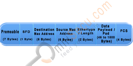
Figure of Structure of an Ethernet Frame

The Ethernet Frame fields are explained below

Preamble: A sequence of 56 bits having alternating 1 and 0 values that are used for synchronization. They serve to give components in the network time to detect the presence of a signal, and being reading the signal before the frame data arrives.

SFD (Start Frame Delimiter): A sequence of 8 bits having the bit configuration 10101011 that indicates the start of the frame.

Source and Destination MAC Addresses: The Source MAC Address is the MAC Address of the device this frame is coming from. The Destination MAC Address is the MAC Address of the device which is going to receive this frame. Both of these fields are 6 bytes long.

MAC address (Layer 2 addresses, physical address or hardware address) is a universally unique identifier, permanently burned in the network card. For Ethernet and Token Ring, these addresses are 48 bits, or six octets (bytes). MAC Addresses are represented in hexadecimal characters because hexadecimal format is easier for humans to read when compared with the binary format. One hexadecimal digit resembles a group of four contiguous binary bits, called a nibble. An example representation of MAC address is AA.F0.C1.E8.13.40.

Length/Type: A 2-byte (16-bit) field contains the number of bytes in the Data field or the nature of the MAC client protocol.

Data: This field contains the actual data transferred from the source device to the destination device. The maximum size of this field is 1500 bytes. If the size of this field is less than 46 bytes, then use of the subsequent "Pad" field is necessary to bring the frame size up to the minimum length.

Pad: If necessary, extra data bytes are appended in this field to bring the frame length up to its minimum size. A minimum Ethernet frame size is 64 bytes from the Destination MAC Address field through the Frame Check Sequence.

Frame Check Sequence: This field contains a 4-byte Cyclic Redundancy Check (CRC) value used for error checking. When a source device assembles a frame, it performs a Cyclic Redundancy Check (CRC) calculation on all fields in the frame except the Preamble, SFD (Start Frame Delimiter), and frame check sequence using a predetermined algorithm. The source device stores the value in this field and transmits it as part of the frame. When the frame is received by the destination device, it performs an CRC test again using the same algorithm. If the CRC value calulated at the destination device does not match the value in the FCS (Frame Check Sequence) field, the destination device will discards the frame, considering this as a transmission error.

To view the MAC Address when you are working with a Windows workstation, run cmd (Start > run > type cmd and Enter). Type the command "ipconfig /all" in the prompt and Enter. Do remember to remove double quotes.

In TCP/IP Network Access Layer lesson, you have learned the sublayers of Datalink Layer. The sublayers of Datalink layer are Media Access Control (MAC) sublayer and Logical Link Control (LLC) sublayer. You also learned about the Ethernet Frame Header, the structure of an Ethernet Frame, different fields in Ethernet Frame header, what is a runt frame and what is a giant frame.

READ MORE

Internet Protocol, or IP, provides an unreliable packet delivery system--each packet is an individual, and is handled separately. Packets can arrive out of order or not at all. The recipient does not acknowledge them, so the sender does not know that the transmission was successful. There are no provisions for flow control--packets can be received faster than they can be used. And packet size is limited.

Transmission Control Protocol (TCP) is a network protocol designed to address these problems. TCP uses IP, but adds a layer of control on top. TCP packets are lost occasionally, just like IP packets. The difference is that the TCP protocol takes care of requesting retransmits to ensure that all packets reach their destination, and tracks packet sequence numbers to be sure that they are delivered in the correct order. While IP packets are independent, with TCP we can use streams along with the standard Java file I/O mechanism.

Think of TCP as establishing a connection between the two endpoints. Negotiation is performed to establish a "socket", and the socket remains open throughout the duration of the communications. The recipient acknowledges each packet, and packet retransmissions are performed by the protocol if packets are missed or arrive out of order. In this way TCP can allow an application to send as much data as it desires and not be subject to the IP packet size limit..
TCP is responsible for breaking the data into packets, buffering the data, resending lost or out of order packets, acknowledging receipt, and controlling rate of data flow by telling the sender to speed up or slow down so that the application never receives more than it can handle.

There are four distinct elements that make a TCP connection unique:

  • IP address of the server
  • IP address of the client
  • Port number of the server
  • Port number of the client
    Each requested client socket is assigned a unique port number while the server port number is always the same. If any of these numbers is different, the socket is different. A server can thus listen to one and only one port, and talk to multiple clients at the same time.

So a TCP connection is somewhat like a telephone connection; you need to know not only the phone number (IP address), but because the phone may be shared by many people at that location, you also need the name or extension of the user you want to talk to at the other end (port number). The analogy can be taken a little further. If you don't hear what the other person has said, a simple request ("What?") will prompt the other end to resend or repeat the phrase, and the connection remains open until someone hangs up.

READ MORE

TCP is a connection oriented stream over an IP network. It guarantees that all sent packets will reach the destination in the correct order. This imply the use of acknowledgement packets sent back to the sender, and automatic retransmission, causing additional delays and a general less efficient transmission then UDP.

UDP a is connection less protocol. Communication is datagram oriented. The integrity is guaranteed only on the single datagram. Datagrams reach destination and can arrive out of order or don't arrive at all. Is more efficient than TCP because it uses non ack. It's generally used for real time communication, where a little percentage of packet loss rate is preferable to the overhead of a TCP connection.


Here I am trying to highlight the difference between these protocols?

Reliability:
TCP is connection-oriented protocol. When a file or message send it will get delivered unless connections fails. If connection lost, the server will request the lost part. There is no corruption while transferring a message.
UDP is connectionless protocol. When you a send a data or message, you don't know if it'll get there, it could get lost on the way. There may be corruption while transferring a message.

Ordered/Unordered:
If you send two messages along a connection i.e. TCP , one after the other, you know the first message will get there first. You don't have to worry about data arriving in the wrong order.
Where as If you send two messages out in UDP, you don't know what order they'll arrive in i.e. no ordered

Heavyweight/Lightweight:
When the low level parts of the TCP "stream" arrive in the wrong order, resend requests have to be sent, and all the out of sequence parts have to be put back together, so requires a bit of work to piece together.

In UDP No ordering of messages, no tracking connections, etc. It's just fire and forget! This means it's a lot quicker, and the network card / OS have to do very little work to translate the data back from the packets.

Streaming/Datagram:
In TCP Data is read as a "stream" with nothing distinguishing where one packet ends and another begins. There may be multiple packets per read call.
In UDP Data is read as a Datagrams: Packets are sent individually and are guaranteed to be whole if they arrive. One packet per one read call.

Examples of TCP:
www (Apache TCP port 80)
e-mail (SMTP TCP port 25 Postfix MTA),
File Transfer Protocol (FTP port 21) and
Secure Shell (OpenSSH port 22) etc.

Examples of UDP:
Domain Name System (DNS UDP port 53),
streaming media applications such as IPTV or movies, Voice over IP (VoIP),
Trivial File Transfer Protocol (TFTP) and
online multiplayer games etc

READ MORE
...