top button
Flag Notify
    Connect to us
      Site Registration

Site Registration

IPv4 - Address Classes.

0 votes
583 views

Internet Protocol hierarchy contains several classes of IP Addresses to be used efficiently in various situation as per the requirement of hosts per network. Broadly, IPv4 Addressing system is divided into 5 classes of IP Addresses. All the 5 classes are identified by the first octet of IP Address.

Internet Corporation for Assigned Names and Numbers - responsible for
assigning IP addresses.

The first octet referred here is the left most of all. The octets numbered as follows depicting dotted decimal notation of IP Address:
enter image description here
Number of networks and number of hosts per class can be derived by this formula:
enter image description here
When calculating hosts IP addresses, 2 IP addresses are decreased because they cannot be assigned to hosts i.e. the first IP of a network is network number and the last IP is reserved for Broadcast IP.

Class A Address

The first bit of the first octet is always set to 0 (zero). Thus the first octet ranges from 1 – 127, i.e.
enter image description here
Class A addresses only include IP starting from 1.x.x.x to 126.x.x.x only. The IP range 127.x.x.x is reserved for loopback IP addresses.

The default subnet mask for Class A IP address is 255.0.0.0 which implies that Class A addressing can have 126 networks (27-2) and 16777214 hosts (224-2).

Class A IP address format thus, is 0NNNNNNN.HHHHHHHH.HHHHHHHH.HHHHHHHH

Class B Address

An IP address which belongs to class B has the first two bits in the first octet set to 10, i.e.
enter image description here
Class B IP Addresses range from 128.0.x.x to 191.255.x.x. The default subnet mask for Class B is 255.255.x.x.

Class B has 16384 (214) Network addresses and 65534 (216-2) Host addresses.

Class B IP address format is, 10NNNNNN.NNNNNNNN.HHHHHHHH.HHHHHHHH

Class C Address

The first octet of Class C IP address has its first 3 bits set to 110, that is
enter image description here
Class C IP addresses range from 192.0.0.x to 192.255.255.x. The default subnet mask for Class B is 255.255.255.x.

Class C gives 2097152 (221) Network addresses and 254 (28-2) Host addresses.

Class C IP address format is 110NNNNN.NNNNNNNN.NNNNNNNN.HHHHHHHH

Class D Address

Very first four bits of the first octet in Class D IP addresses are set to 1110, giving a range of
enter image description here
Class D has IP address rage from 224.0.0.0 to 239.255.255.255. Class D is reserved for Multicasting. In multicasting data is not destined for a particular host, that's why there is no need to extract host address from the IP address, and Class D does not have any subnet mask.

Class E Address

This IP Class is reserved for experimental purposes only like for R&D or Study. IP addresses in this class ranges from 240.0.0.0 to 255.255.255.254. Like Class D, this class too is not equipped with any subnet mask.

posted Jul 14, 2014 by Vrije Mani Upadhyay

  Promote This Article
Facebook Share Button Twitter Share Button LinkedIn Share Button


Related Articles

Private IP Addresses

Every class of IP, (A, B & C) has some addresses reserved as Private IP addresses. These IPs can be used within a network, campus, company and are private to it. These addresses cannot be routed on Internet so packets containing these private addresses are dropped by the Routers.
Private IP Addresses
In order to communicate with outside world, Internet, these IP addresses must have to be translated to some public IP addresses using NAT process or Web Proxy server can be used.

The sole purpose to create separate range of private addresses is to control assignment of already-limited IPv4 address pool. By using private address range within LAN, the requirement of IPv4 addresses has globally decreased significantly. It has also helped delaying the IPv4 address exhaustion.

IP class, while using private address range, can be chosen as per the size and requirement of the organization. Larger organization may choose class A private IP address range where smaller may opt for class C. These IP addresses can be further sub-netted be assigned to departments within an organization.

Loopback IP Addresses

The IP address range 127.0.0.0 – 127.255.255.255 is reserved for loopback i.e. a Host’s self-address. Also known as localhost address. This loopback IP address is managed entirely by and within the operating system. Using loopback addresses, enable the Server and Client processes on a single system to communicate with each other. When a process creates a packet with destination address as loopback address, the operating system loops it back to itself without having any interference of NIC.

Data sent on loopback is forward by the operating system to a virtual network interface within operating system. This address is mostly used for testing purposes like client-server architecture on a single machine. Other than that, if a host machine can successfully ping 127.0.0.1 or any IP from loopback range, implies that the TCP/IP software stack on the machine is successfully loaded and working.

Link-local Addresses

In case of the Host is not able to acquire an IP address from DHCP server and it has not been assigned any IP address manually, the host can assign itself an IP address from a range of reserved Link-local addresses. Link local address range is 169.254.0.0 - 169.254.255.255.

Assume a network segment where all systems are configured to acquire IP addresses from a DHCP server connected to the same network segment. If the DHCP server is not available, no host on the segment will be able to communicate to any other. Windows (98 or later), and Mac OS (8.0 or later) support this functionality of self-configuration of Link-local IP address. In absence of DHCP server, every host machine randomly chooses an IP address from the above mentioned range and then checks to ascertain by means of ARP, if some other host also has not configured himself with the same IP address. Once all hosts are using link local addresses of same range, they can communicate to each other.

These IP addresses cannot help system to communicate when they do not belong to the same physical or logical segment. These IPs are also not routable.

READ MORE

In This Section we have Describe that how to subnet a Network Address.

Internet Service Providers may face a situation where they need to allocate IP subnets of different sizes as per the requirement of customer. One customer may ask Class C subnet of 3 IP addresses and another may ask for 10 IPs. For an ISP, it is not feasible to divide the IP addresses into fixed size subnets, rather he may want to subnet the subnets in such a way which results in minimum wastage of IP addresses.

For example, an administrator have 192.168.1.0/24 network. The suffix /24 (pronounced as "slash 24") tells the number of bits used for network address. He is having three different departments with different number of hosts. Sales department has 100 computers, Purchase department has 50 computers, Accounts has 25 computers and Management has 5 computers. In CIDR, the subnets are of fixed size. Using the same methodology the administrator cannot fulfill all the requirements of the network.

The following procedure shows how VLSM can be used in order to allocate department-wise IP addresses as mentioned in the example.

Step - 1

Make a list of Subnets possible.
Subnetting List

Step - 2

Sort the requirements of IPs in descending order (Highest to Lowest).

  Sales         100
  Purchase      50
  Accounts      25
  Management    5

Step - 3

Allocate the highest range of IPs to the highest requirement, so let's assign 192.168.1.0 /25 (255.255.255.128) to Sales department. This IP subnet with Network number 192.168.1.0 has 126 valid Host IP addresses which satisfy the requirement of Sales Department. The subnet Mask used for this subnet has 10000000 as the last octet.

Step - 4

Allocate the next highest range, so let's assign 192.168.1.128 /26 (255.255.255.192) to Purchase department. This IP subnet with Network number 192.168.1.128 has 62 valid Host IP Addresses which can be easily assigned to all Purchase department's PCs. The subnet mask used has 11000000 in the last octet.

Step - 5

Allocate the next highest range, i.e. Accounts. The requirement of 25 IPs can be fulfilled with 192.168.1.192 /27 (255.255.255.224) IP subnet, which contains 30 valid host IPs. The network number of Accounts department will be 192.168.1.192. The last octet of subnet mask is 11100000.

Step - 6

Allocate next highest range to Management. The Management department contains only 5 computers. The subnet 192.168.1.224 /29 with Mask 255.255.255.248 has exactly 6 valid host IP addresses. So this can be assigned to Management. The last octet of subnet mask will contain 11111000.

By using VLSM, the administrator can subnet the IP subnet such a way that least number of IP addresses are wasted. Even after assigning IPs to every department, the administrator, in this example, still left with plenty of IP addresses which was not possible if he has used CIDR.

READ MORE

In earlier topic we have describe about IP Address Classess and Now we are discribing that how to Subnet Class A,B,C IP Address.
Each IP class is equipped with its own default subnet mask which bounds that IP class to have prefixed number of Networks and prefixed number of Hosts per network. Classful IP addressing does not provide any flexibility of having less number of Hosts per Network or more Networks per IP Class.

CIDR or Classless Inter Domain Routing provides the flexibility of borrowing bits of Host part of the IP address and using them as Network in Network, called Subnet. By using subnetting, one single Class A IP addresses can be used to have smaller sub-networks which provides better network management capabilities.

Class A Subnets

In Class A, only the first octet is used as Network identifier and rest of three octets are used to be assigned to Hosts (i.e. 16777214 Hosts per Network). To make more subnet in Class A, bits from Host part are borrowed and the subnet mask is changed accordingly.

For example, if one MSB (Most Significant Bit) is borrowed from host bits of second octet and added to Network address, it creates two Subnets (2^1=2) with (2^23-2) 8388606 Hosts per Subnet.

The Subnet mask is changed accordingly to reflect subnetting. Given below is a list of all possible combination of Class A subnets:
Class A Subnets
In case of subnetting too, the very first and last IP address of every subnet is used for Subnet Number and Subnet Broadcast IP address respectively. Because these two IP addresses cannot be assigned to hosts, Sub-netting cannot be implemented by using more than 30 bits as Network Bits which provides less than two hosts per subnet.

Class B Subnets

By Default, using Classful Networking, 14 bits are used as Network bits providing (214) 16384 Networks and (216-1) 65534 Hosts. Class B IP Addresses can be subnetted the same way as Class A addresses, by borrowing bits from Host bits. Below is given all possible combination of Class B subnetting:
Class B Subnets

Class C Subnets

Class C IP addresses normally assigned to a very small size network because it only can have 254 hosts in a network. Given below is a list of all possible combination of subnetted Class B IP address:
Class C Subnetts

READ MORE

IPv4 supports three different type of addressing modes:

Unicast Addressing Mode:

In this mode, data is sent only to one destined host. The Destination Address field contains 32- bit IP address of the destination host. Here client sends data to the targeted server:
Unicast Addressing Mode

Broadcast Addressing Mode:

In this mode the packet is addressed to all hosts in a network segment. The Destination Address field contains special broadcast address i.e. 255.255.255.255. When a host sees this packet on the network, it is bound to process it. Here client sends packet, which is entertained by all the Servers:
Broadcast Addressing Mode

Multicast Addressing Mode:

This mode is a mix of previous two modes, i.e. the packet sent is neither destined to a single host nor all the host on the segment. In this packet, the Destination Address contains special address which starts with 224.x.x.x and can be entertained by more than one host.
Multicast Addressing Mode

Here a server sends packets which are entertained by more than one Servers. Every network has one IP address reserved for network number which represents the network and one IP address reserved for Broadcast Address, which represents all the host in that network.

Hierarchical Addressing Scheme

IPv4 uses hierarchical addressing scheme. An IP address which is 32-bits in length, is divided into two or three parts as depicted:
Hierarchical Addressing Scheme

A single IP address can contain information about the network and its sub-network and ultimately the host. This scheme enables IP Address to be hierarchical where a network can have many sub-networks which in turn can have many hosts.

Subnet Mask

The 32-bit IP address contains information about the host and its network. It is very necessary to distinguish the both. For this, routers use Subnet Mask, which is as long as the size of the network address in the IP address. Subnet Mask is also 32 bits long. If the IP address in binary is ANDed with its Subnet Mask, the result yields the Network address. For example, say the IP Address 192.168.1.152 and the Subnet Mask is 255.255.255.0 then
Subnet Mask

This way Subnet Mast helps extract Network ID and Host from an IP Address. It can be identified now that 192.168.1.0 is the Network number and 192.168.1.152 is the host on that network.

Binary Representation

The positional value method is the simplest form of converting binary from decimal value. IP address is 32 bit value which is divided into 4 octets. A binary octet contains 8 bits and the value of each bit can be determined by the position of bit value '1' in the octet.
Binary Representation

Positional value of bits is determined by 2 raised to power (position – 1), that is the value of a bit 1 at position 6 is 26-1 that is 25 that is 32. The total value of the octet is determined by adding up the positional value of bits. The value of 11000000 is 128+64 = 192. Some Examples are shown in the table below:
enter image description here

READ MORE

Internet Protocol being a layer-3 protocol (OSI) takes data Segments from layer-4 (Transport) and divides it into what’s called packet. IP packet encapsulates data unit received from above layer and adds its own header information.
enter image description here

The encapsulated data is referred to as IP Payload. IP header contains all the necessary information to deliver the packet at the other end.
enter image description here

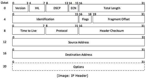
IP header includes many relevant information including Version Number, which, in this context, is 4. Other details are as follows:

Version: Version no. of Internet Protocol used (e.g. IPv4)

IHL: Internet Header Length, Length of entire IP header

DSCP: Differentiated Services Code Point, This is Type of Service.

ECN: Explicit Congestion Notification, carries information about the congestion seen in the route.

Total Length: Length of entire IP Packet (including IP header and IP Payload)

Identification: If IP packet is fragmented during the transmission, all the fragments contain same identification no. to identify original IP packet they belong to.

Flags: As required by the network resources, if IP Packet is too large to handle these ‘flags’ tell that if they can be fragmented or not. In this 3-bit flag, the MSB is always set to ‘0’.

Fragment Offset: This offset tells the exact position of the fragment in the original IP Packet.

Time to Live: To avoid looping in the network, every packet is sent with some TTL value set, which tells the network how many routers (hops) this packet can cross. At each hop, its value is decremented by one and when the value reaches zero, the packet is discarded.

Protocol: Tells the Network layer at the destination host, to which Protocol this packet belongs to, i.e. the next level Protocol. For example protocol number of ICMP is 1, TCP is 6 and UDP is 17.

Header Checksum: This field is used to keep checksum value of entire header which is then used to check if the packet is received error-free.

Source Address: 32-bit address of the Sender (or source) of the packet.

Destination Address: 32-bit address of the Receiver (or destination) of the packet.

Options: This is optional field, which is used if the value of IHL is greater than 5. These options may contain values for options such as Security, Record Route, Time Stamp etc.

READ MORE

An IPv4 address transfer can only happen when the source account initiates the process. At the same time, the recipient account would be required to acknowledge the transfer of the IP address within a month or the request would be canceled by APNIC. After both the parties agree to the IPv4 transfer, APNIC Hostmasters would evaluate the request and approve it if it meets all the terms and conditions specified by the Regional Internet Registry.

Generally, APNIC Hostmasters takes around 1 – 2 working days to respond to an IPv4 address transfer request. Once it is approved, the IPv4 addresses to be transferred would show up on the transfer log on the APNIC website. However, the RIR might ask for additional information for clarification before the transfer is completed.

The source account should be open before lodging a request for IPv4 transfer. If there was any renewal invoice issued, the account holder must settle it before submitting the IPv4 address transfer request. After the transfer is done, the source account holder would have no right to oversee the IPv4 addresses. Note that APNIC cannot undo the transfer or offer any membership fee refund on account of an IPv4 transfer. However, the source account is allowed to cancel the IPv4 address transfer request through MyAPNIC before the recipient account accepts it.

IPv4 Address

IPv4 Transfers Facts

APNIC usually asks the recipient account to give more information to explain the IPv4 transfer. Once the transfer is complete, the recipient account would be responsible to manage the IPv4 addresses as well as pay the fees associated with its renewal. Even if the recipient account were in another region, APNIC can transfer the IPv4 addresses to the relevant RIR. Yet, the policies regarding IPv4 transfer might vary a bit here, depending upon the region of the recipient account.

To receive an IPv4 transfer from a different RIR country, the recipient account in the Asia Pacific would need to file a request for pre-approval from APNIC. As soon as APNIC receives and approves the pre-approval, the recipient account would need to appeal APNIC to include the particulars about the recipient account on the IPv4 Address Transfer Listing Service page of their website. It is to be noted that pre-approval expires within two years, so this step should be taken as early as possible to make the IPv4 transfer smooth.

After the recipient and the source account holder reach an agreement, the recipient account holder can provide the applicable details to the source RIR as required. APNIC would contact the recipient to finalize the transfer when it gets the transfer request from the source account’s RIR.

READ MORE
...