With the Fast Changing Landscape mobility and convergence in all communications services, Handovers plays a significant role to get them succeed. In terms of cost effectiveness, enhanced features, location independence and ease of use, not only within a Long Term Evolution (LTE) network but also between networks including UMTS, GSM and CDMA.
There are two ways by which handovers can be decided:
- Network Evaluated: the network makes the handover decision
- Mobile Evaluated: the UE makes the handoff decision and informs the network about it. In this instance, the final decision will be made by the network based upon on the Radio Resource Management.
In LTE there are three types of handovers:
- Intra-LTE: Handover happens within the current LTE nodes (intra-MME and Intra-SGW).
- Inter-LTE: Handover happens toward the other LTE nodes (inter-MME and Inter-SGW).
- Inter-RAT: Handover between different radio technology networks, for example GSM/UMTS and
UMTS.
We will first look on Intra-LTE handovers with X2AP signaling then in continue articles will explain further:
- Intra-LTE (Intra-MME / SGW) Handover Using the X2 Interface:
In this case the assumption is MME and S-GW is unchanged. The presence of IP connectivity between the Serving GW and the source eNodeB, as well as between the Serving GW and the target eNodeB is assumed. Only the eNodeB's will be changing not the MME and S-GW. eNodeB's will talk with each other through X2 interface. There is no involvement of EPC. It means the preparation of resources and completion of handovers, these all messages will be exchanged in between Source eNodeB and target eNodeB.
See the diagram:
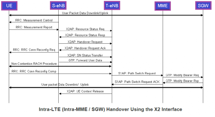
Now Let me explain the diagram step-wise:
- A complete data call been established. Data Packets are getting exchange in Network from DL as well as Uplink.
- The network will set the thresholds with MeasurementControlReq message and will instruct the UE when it detects the thresholds it should report to the network.
- Now, UE has detected the thresholds and as communicated it would send the report to Serving eNodeB and now the decision of handover can be made using the Handover Algorithm. Each operator has its own handover algorithm, on basis of that it will make the handover to Target eNodeB.
- Before the Source eNodeB continue the handover procedure using X2 interface, It has to check either the target eNodeB has sufficient resources or not. To check this Source eNodeB will send the RESIURCE STATUS REQUEST message to find out the load on target eNodeB. (Note: This is an optional check, depends upon the implementation).
- After the check Source eNodeB will issue the Handover request to Target eNodeB including necessary information to prepare the handover at target side (e.g., UE Context which includes the Security Context and RB Context (including E-RAB to RB Mapping) and the Target cell info).
- Now target eNodeB will confirm the resources availability, then reserves it for UE and acknowledge the request with message HANDOVER REQUEST ACKNOWLEDGE including a transparent container to be sent to the UE as an RRC message to perform the handover. The container includes a new C-RNTI, T-eNB security algorithm identifiers for the selected security algorithms, and may include a dedicated RACH preamble and possibly some other parameters (i.e., access parameters, SIBs, etc.).
- The S-eNB generates the RRC message to perform the handover, i.e, RRCCONNECTION RECONFIGURATION message including the mobilityControlInformation. The S-eNB performs the necessary integrity protection and ciphering of the message and sends it to the UE.
- The S-eNB sends the eNB STATUS TRANSFER message to the T-eNB to convey the PDCP and HFN status of the E-RABs.
- The S-eNB starts forwarding the downlink data packets to the T-eNB for all the data bearers (which are being established in the T-eNB during the HANDOVER REQ message processing).
- In the meantime, the UE tries to access the T-eNB cell using the non-contention-based Random Access Procedure. If it succeeds in accessing the target cell, it sends the RRC CONNECTION RECONFIGURATION COMPLETE to the T-eNB.
- The T-eNB sends a PATH SWITCH REQUEST message to the MME to inform it that the UE has changed cells, including the TAI+ECGI of the target. The MME determines that the SGW can continue to serve the UE.
- The MME sends a MODIFY BEARER REQUEST (eNodeB address and TEIDs for downlink user plane for the accepted EPS bearers) message to the SGW. If the PDN GW requested the UE’s location info, the MME also includes the User Location Information IE in this message.
- The SGW sends the downlink packets to the target eNB using the newly received addresses and TEIDs (path switched in the downlink data path to T-eNB) and the MODIFY BEARER RESPONSE to the MME.
- The serving gateway sends one or more "end marker" packets on the old path to serving eNodeB and then can release any user plane/TNL resources toward the serving eNodeB.
- The MME responds to the Target eNodeB with a PATH SWITCH REQ ACK message to notify the completion of the handover.
- After all the procedures target eNodeB request the source eNodeB to release all the resources of UE with message of X2 UE CONTEXT RELEASE. After this message the Handover is completely done.