top button
Flag Notify
    Connect to us
      Site Registration

Site Registration

LTE attach procedure Part1

+4 votes
1,514 views

There is a defined call flow for Long Term Evolution (LTE) when it comes to the network architecture; however, there is also an LTE attach procedure within that call flow. This LTE attach procedure is an important part of the structure and deserve special attention.

In SAE/EPS article, we looked at LTE network architecture; in this article, we will look at end-to-end initial UE attach signaling.

What is different with LTE UE initial attach ? In LTE, initial attach is combined with (default) PDN (IP) connectivity. You can call this default PDN (IP) connectivity as default (or basic or initial) PDP context activation. This default connectivity is always of non-guaranted bit rate type (basically something which handles mostly bursty internet traffic). This default connectivity is called "default bearer". LTE no more use NAS terminology of "PDP Context" for "Sessions". By the way, LTE NAS consists only of Mobility Management (EMM) and Session Management (ESM). Additional PDP Contexts or Sessions (with different QoSs than default bearers) are called "dedicated bearers". Yes, it is misleading to call it "dedicated"

The attach procedure may trigger one or multiple dedicated bearer establishment procedures to designate a dedicated EPS bearer for that UE. The UE may also make a request for an IP address allocation during the LTE attach procedure. Once this happens, the next steps begin and bearers are largely involved. Wired n Wireless explains the bearer request and response messages below:

Create Default Bearer Request: MME —-> S-GW
MME selects a S-GW and allocates an EPS bearer identity for default bearer associated with UE. Next, it sends a “create default bearer request.” This message provides a subscribed APN AMBR for the APN. MSISDN is included if the attach type indicates handover. Then, selection mode indicates that a subscribed APN was selected. Charging characteristics indicates which kind of charging the bearer context is liable for. hen it sends Create Default Bearer Request with following IEs: IMSI, MSISDN, MME TEID for Control Plane, PDN GW address, PDN Address, APN, RAT Type, Default EPS bearer QoS, PDN Type, APN-AMBR, EPS Bearer Identity (EBI), Protocol COnfiguration Options, Handover Indication, ME identity, User Location Information (ECGI), MS Info Change Reporting Support Indication, Selection Mode, Charging Characteristics, Trace Reference, Trace Type, Trigger ID, OMC identity, Maximum APN Restriction, Dual Address Bearer Flag, Protocol over S5/S8.

Create Default Bearer Request : S-GW ——–>PDN-GW
The S-GW creates a new entry in its EPS bearer table and sends a create default bearer request message to PDN GW, indicated by the PDN GW address received in the previous step. This message contains IMSI, MSISDN, APN, S-GW address for User Plane, S-GW TEID of the User Plane, S-GW TEID of the Control plane, RAT Type, Default EPS bearer QoS, PDN Type, PDN Address, Subscribed APN-AMBR, EPS bearer identity, Protocol Configuration Options, Handover Indication, ME Identity, user Location Information (ECGI), MS Info change Reporting SUpport Indication, Selection Mode, Charging Characteristics, Trace Reference, Trace Type, Trigger ID, OMC Identity, Max APN Restriction
Dual Address Bearer Flag.

Create Default Bearer Response : PDN-GW ——> S-GW:
The P-GW creates a new entry in its EPS bearer context table and generates a charging ID. This new entry allows the P-GW to route user plane PDU’s between the S-GW and the packet data network, allowing them to start charging. The PDN-GW returns a create default bearer response with following IE’s: PDN-GW address for the user plane, PDN GW TEID of the user plane, PDN GW TEID of the control plane, PDN Type, PDN address, EPS Bearer Identity, EPS bearer QoS, Protocol Configuration Options, Charging ID, Prohibit payload compression, APN Restriction Cause, MS Info Change Reporting Action, APN AMBR.

Create Default Bearer Response : S-GW ——–> MME
Finally, S-GW returns a create default bearer response to MME.

Just like "Secondary PDP Context" in GPRS/UMTS, dedicated bearer has same PDN (IP) address as default bearer and specific QoS. Yes, TFT (Traffic Flow Template) is utilised here (UE and PGW) too ! QoS is defined differently in LTE (check out 3GPP TS 36.300 section 13 and 23.401, section 4.7.3).

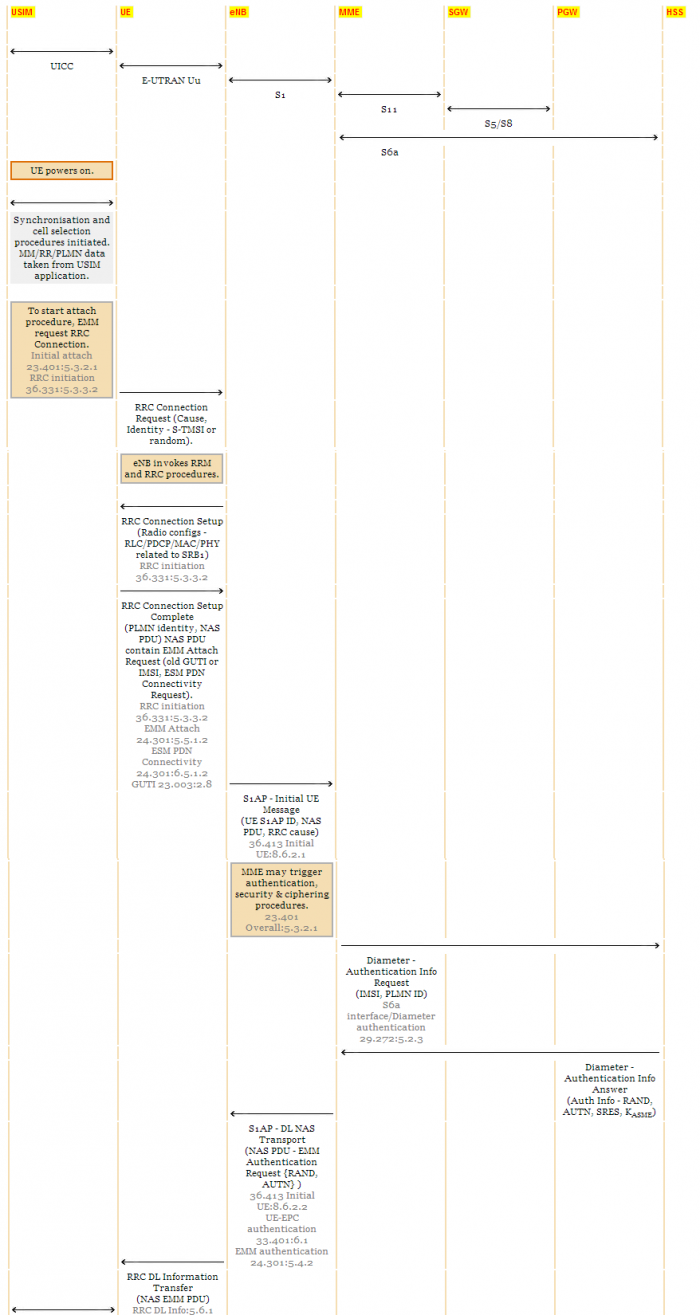
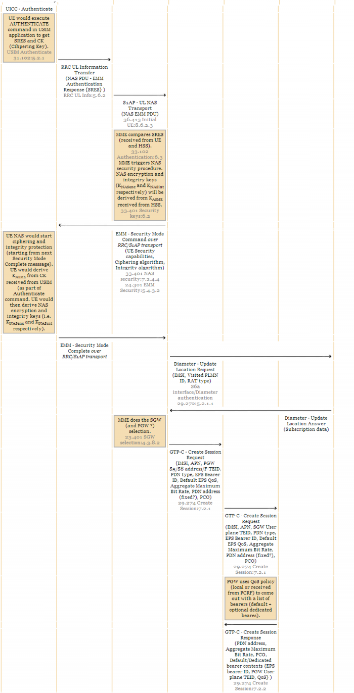
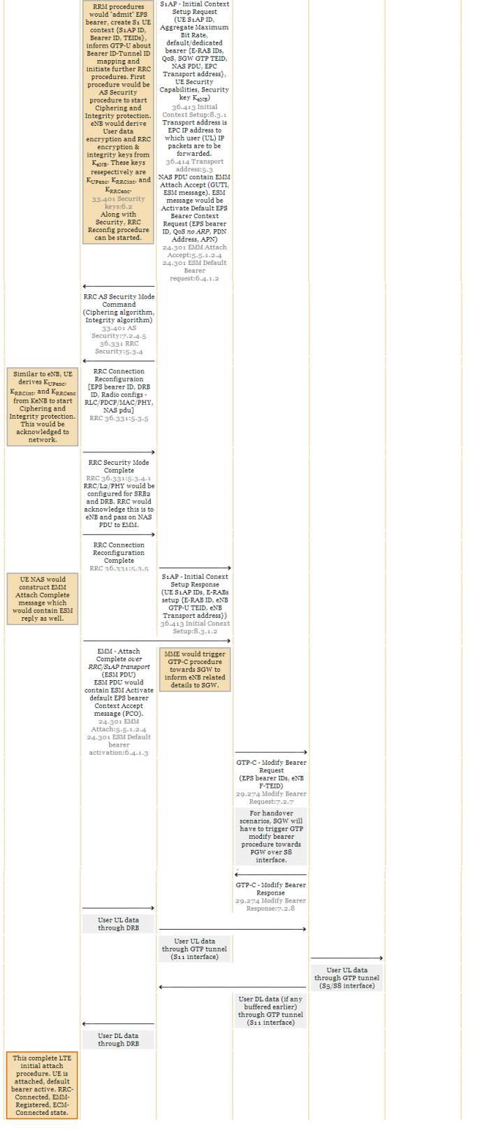
Below is a end-to-end signaling diagram for UE initial attach. I have included lot of specification references to dig in further.

LTE Attach Procedure image1

Lte Attach Procedure image2

LTE Attach Procedure image3

posted May 13, 2014 by anonymous

  Promote This Article
Facebook Share Button Twitter Share Button LinkedIn Share Button


Related Articles

This is continuation from my previous article. Please go through from my previous article.
http://tech.queryhome.com/43577/lte-attach-procedure-part1

Here’s the LTE Attach Procedure Call Flow, broken down into steps, derived by 3GPP.

Step 1. The UE initiates the attach procedure by transmitting an attach request to the eNodeB.
Step 2. The eNodeB derives the MME from the RRC parameters carrying the old GUMMEI and the indicated Selected Network.
Step 3. If the UE identifies itself with GUTI and the MME has changed since detach, the new MME uses the GUTI received from the UE to derive the old MME/SGSN address, and send an Identification Request to the old MME/SGSN to request the IMSI.
Step 4. If the UE is unknown in both the old MME/SGSN and new MME, the new MME sends an Identity Request to the UE to request the IMSI. The UE responds with Identity Response (IMSI).
Step 5a. If no UE context for the UE exists anywhere in the network, if the Attach Request (sent in step 1) was not integrity protected, or if the check of the integrity failed, then authentication and NAS security setup to activate integrity protection and NAS ciphering are mandatory.
Step 5b. The ME Identity shall be retrieved from the UE.
Step 6. If the UE has set the Ciphered Options Transfer Flag in the Attach Request message, the Ciphered Options i.e. PCO or APN or both, shall now be retrieved from the UE.
Step 7. If there are active bearer contexts in the new MME for this particular UE (i.e. the UE re-attaches to the same MME without having properly detached before), the new MME deletes these bearer contexts by sending Delete Session Request (LBI) messages to the GWs involved.
Step 8. If the MME has changed since the last detach, or if there is no valid subscription context for the UE in the MME, the MME sends an Update Location Request message to the HSS.
Step 9. The HSS sends Cancel Location (IMSI, Cancellation Type) to the old MME. \
Step 10. If there are active bearer contexts in the old MME/SGSN for this particular UE, the old MME/SGSN deletes these bearer contexts by sending Delete Session Request (LBI) messages to the GWs involved.
Step 11. The HSS acknowledges the Update Location message by sending an Update Location Ack message to the new MME.
Step 12. For an Emergency Attach situation, the MME applies the parameters from MME Emergency Configuration Data for the emergency bearer establishment performed in this step and any potentially stored IMSI related subscription data are ignored by the MME.
Step 13. The Serving GW creates a new entry in its EPS Bearer table and sends a Create Session Request message to the PDN GW indicated by the PDN GW address received in the previous step.
Step 14. If dynamic PCC is deployed and the Handover Indication is not present, the PDN GW performs an IP-CAN Session Establishment procedure.
Step 15. The PGW creates a new entry in its EPS bearer context table and generates a Charging Id.
Step 16. If the MS Info Change Reporting Action (Start) or the CSG Information Reporting Action (Start) are received for this bearer context, then the SGW stores this for the bearer context and the SGW reports to that PGW whenever a UE’s location and/or User CSG information change occurs that meets the PGW request.
Step 17. If an APN Restriction is received, then the MME shall store this value for the Bearer Context and the MME shall check this received value with the stored value for the Maximum APN Restriction to ensure there are no conflicts between values.
Step 18. The eNodeB sends the RRC Connection Reconfiguration message including the EPS Radio Bearer Identity to the UE, and the Attach Accept message will be sent along to the UE.
Step 19. The UE sends the RRC Connection Reconfiguration Complete message to the eNodeB.
Step 20. The eNodeB sends the Initial Context Response message to the new MME.
Step 21. The UE sends a Direct Transfer message to the eNodeB, which includes the Attach Complete message.
Step 22. The eNodeB forwards the Attach Complete message to the new MME in an Uplink NAS Transport message.
Step 23. Upon reception of both, the Initial Context Response message in step 20 and the Attach Complete message in step 22, the new MME sends a Modify Bearer Request message to the Serving GW.
Step 23a. If the Handover Indication is included in step 23, the Serving GW sends a Modify Bearer Request (Handover Indication) message to the PDN GW to prompt the PDN GW to tunnel packets from non 3GPP IP access to 3GPP access system and immediately start routing packets to the Serving GW for the default and any dedicated EPS bearers established.
Step 23b. The PDN GW acknowledges by sending Modify Bearer Response to the Serving GW.
Step 24. The Serving GW acknowledges by sending Update Bearer Response (EPS Bearer Identity) message to the new MME.
Step 25. After the MME receives Modify Bearer Response (EPS Bearer Identity) message, if Request Type does not indicate handover and an EPS bearer was established and the subscription data indicates that the user is allowed to perform handover to non-3GPP accesses, and if the MME selected a PDN GW that is different from the PDN GW identity which was indicated by the HSS in the PDN subscription context, the MME shall send a Notify Request including the APN and PDN GW identity to the HSS for mobility with non-3GPP accesses. The message shall include information that identifies the PLMN in which the PDN GW is located.
Step 26. The HSS stores the APN and PDN GW identity pair and sends a Notify Response to the MME.

READ MORE
...