Those who are going to read this article i want to inform them that first part of this article is written here. I suggest you to read that first, because I am going to continue from there as i left.
In my previous article I ended up with types of carrier aggregation ( http://tech.queryhome.com/38321/lte-advanced-carrier-aggregation-explained ) Continuing that..

Figure: These are different types of carrier aggregation.
and will elaborate the same thing further:
Radio Interface Aspects for Carrier aggregation:
Intra-band: This form of carrier aggregation uses a single band. There are two main formats for this type of carrier aggregation:
a. Contiguous: The Intra-band contiguous carrier aggregation is the easiest form of LTE carrier aggregation to implement. Here the carriers are adjacent to each other.
The aggregated channel can be considered by the terminal as a single enlarged channel from the RF viewpoint. In this instance, only one transceiver is required within the terminal or UE, whereas more are required where the channels are not adjacent. However as the RF bandwidth increases it is necessary to ensure that the UE in particular is able to operate over such a wide bandwidth without a reduction in performance. Although the performance requirements are the same for the base station, the space, power consumption, and cost requirements are considerably less stringent, allowing greater flexibility in the design. Additionally for the base station, multi-carrier operation, even if non-aggregated, is already a requirement in many instances, requiring little or no change to the RF elements of the design. Software upgrades would naturally be required to cater for the additional capability.
b. Non-contiguous: Non-contiguous intra-band carrier aggregation is somewhat more complicated than the instance where adjacent carriers are used. No longer can the multi-carrier signal be treated as a single signal and therefore two transceivers are required. This adds significant complexity, particularly to the UE where space, power and cost are prime considerations.
The most simple way for an operator to arrange aggregation would be to use contiguous component carriers within the same operating frequency band (as defined for LTE Rel-8/9), so called intra-band contiguous. A contiguous bandwidth wider than 20 MHz is not a likely scenario given frequency allocations today, however it can be common when new spectrum bands like 3.5 GHz are allocated in the future in various parts of the world. The spacing between center frequencies of contiguously aggregated CCs is a multiple of 300 kHz to be compatible with the 100 kHz frequency raster of Release-8/9 and preserving orthogonally of the subcarriers with 15 kHz spacing.
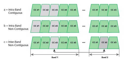
c. Inter-band non-continuous:
Most operators in North America or Europe are currently facing the problem of a fragmented spectrum. The non-contiguous allocation has been specified to fit those scenarios, the allocation could either be intra-band, i.e. the component carriers belong to the same operating frequency band, but have a gap or gaps in between, or it could be inter-band, in which case the component carriers belong to different operating frequency bands.
This form of carrier aggregation uses different bands. It will be of particular use because of the fragmentation of bands - some of which are only 10 MHz wide. For the UE it requires the use of multiple transceivers within the single item, with the usual impact on cost, performance and power. In addition to this there are also additional complexities resulting from the requirements to reduce intermodulation and cross modulation from the two transceivers
The current standards allow for up to five 20 MHz carriers to be aggregated, although in practice two or three is likely to be the practical limit. These aggregated carriers can be transmitted in parallel to or from the same terminal, thereby enabling a much higher throughput to be obtained.