top button
Flag Notify
    Connect to us
      Site Registration

Site Registration

EUTRAN: A complete SnapShot

+3 votes
2,629 views

The E-UTRAN handles the radio communications between the mobile and the evolved packet core and just has one component, the evolved base stations, called eNodeB or eNB. Each eNB is a base station that controls the mobiles in one or more cells. The base station that is communicating with a mobile is known as its serving eNB. LTE Mobile communicates with just one base station and one cell at a time and there are following two main functions supported by eNB:
- The eBN sends and receives radio transmissions to all the mobiles using the analogue and digital signal processing functions of the LTE air interface.
- The eNB controls the low-level operation of all its mobiles, by sending them signalling messages such as handover commands.

Each eBN connects with the EPC by means of the S1 interface and it can also be connected to nearby base stations by the X2 interface, which is mainly used for signalling and packet forwarding during handover.
A home eNB (HeNB) is a base station that has been purchased by a user to provide femtocell coverage within the home. A home eNB belongs to a closed subscriber group (CSG) and can only be accessed by mobiles with a USIM that also belongs to the closed subscriber group.

Protocol Architecture
Protocol Structure

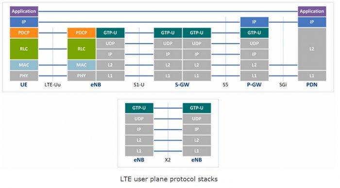
Physical Layer (Layer 1) Physical Layer carries all information from the MAC transport channels over the air interface. Takes care of the link adaptation (AMC), power control, cell search (for initial synchronization and handover purposes) and other measurements (inside the LTE system and between systems) for the RRC layer.

Medium Access Layer (MAC) MAC layer is responsible for Mapping between logical channels and transport channels, Multiplexing of MAC SDUs from one or different logical channels onto transport blocks (TB) to be delivered to the physical layer on transport channels, de multiplexing of MAC SDUs from one or different logical channels from transport blocks (TB) delivered from the physical layer on transport channels, Scheduling information reporting, Error correction through HARQ, Priority handling between UEs by means of dynamic scheduling, Priority handling between logical channels of one UE, Logical Channel prioritization.

Radio Link Control (RLC) RLC operates in 3 modes of operation: Transparent Mode (TM), Unacknowledged Mode (UM), and Acknowledged Mode (AM).

RLC Layer is responsible for transfer of upper layer PDUs, error correction through ARQ (Only for AM data transfer), Concatenation, segmentation and reassembly of RLC SDUs (Only for UM and AM data transfer).

RLC is also responsible for re-segmentation of RLC data PDUs (Only for AM data transfer), reordering of RLC data PDUs (Only for UM and AM data transfer), duplicate detection (Only for UM and AM data transfer), RLC SDU discard (Only for UM and AM data transfer), RLC re-establishment, and protocol error detection (Only for AM data transfer).

Radio Resource Control (RRC) The main services and functions of the RRC sublayer include broadcast of System Information related to the non-access stratum (NAS), broadcast of System Information related to the access stratum (AS), Paging, establishment, maintenance and release of an RRC connection between the UE and E-UTRAN, Security functions including key management, establishment, configuration, maintenance and release of point to point Radio Bearers.

Packet Data Convergence Control (PDCP) PDCP Layer is responsible for Header compression and decompression of IP data, Transfer of data (user plane or control plane), Maintenance of PDCP Sequence Numbers (SNs), In-sequence delivery of upper layer PDUs at re-establishment of lower layers, Duplicate elimination of lower layer SDUs at re-establishment of lower layers for radio bearers mapped on RLC AM, Ciphering and deciphering of user plane data and control plane data, Integrity protection and integrity verification of control plane data, Timer based discard, duplicate discarding, PDCP is used for SRBs and DRBs mapped on DCCH and DTCH type of logical channels.

Non Access Stratum (NAS) Protocols The non-access stratum (NAS) protocols form the highest stratum of the control plane between the user equipment (UE) and MME.

NAS protocols support the mobility of the UE and the session management procedures to establish and maintain IP connectivity between the UE and a PDN GW.

Data Flow Between Layers in EUTRAN
Below is a logical digram of E-UTRAN Protocol layers with a depiction of data flow through various layers:

Data Flow

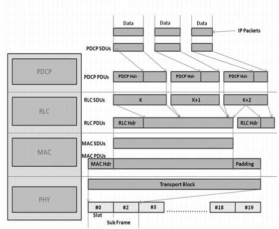
Packets received by a layer are called Service Data Unit (SDU) while the packet output of a layer is referred to by Protocol Data Unit (PDU). Let's see the flow of data from top to bottom:

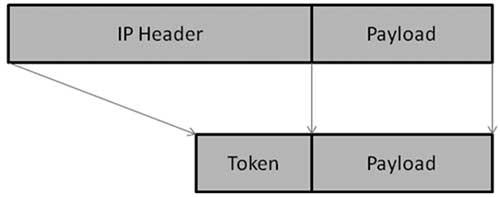
  • IP Layer submits PDCP SDUs (IP Packets) to the PDCP layer. PDCP layer does header compression and adds PDCP header to these PDCP SDUs. PDCP Layer submits PDCP PDUs (RLC SDUs) to RLC layer.

PDCP Header Compression: PDCP removes IP header (Minimum 20 bytes) from PDU, and adds Token of 1-4 bytes. Which provides a tremendous savings in the amount of header that would otherwise have to go over the air.

SDU

  • RLC layer does segmentation of these SDUS to make the RLC PDUs. RLC adds header based on RLC mode of operation. RLC submits these RLC PDUs (MAC SDUs) to the MAC layer.

RLC Segmentation: If an RLC SDU is large, or the available radio data rate is low (resulting in small transport blocks), the RLC SDU may be split among several RLC PDUs. If the RLC SDU is small, or the available radio data rate is high, several RLC SDUs may be packed into a single PDU.

  • MAC layer adds header and does padding to fit this MAC SDU in TTI. MAC layer submits MAC PDU to physical layer for transmitting it onto physical channels.

  • Physical channel transmits this data into slots of sub frame.

posted Feb 17, 2014 by Meenal Mishra

  Promote This Article
Facebook Share Button Twitter Share Button LinkedIn Share Button


Related Articles

The information flows between the different protocols are known as channels and signals. In LTE we have following three classification of channels:

Logical Channels Define what-type of information is transmitted over the air, i.e. traffic channels, control channels, system broadcast, etc. Data and signaling messages are carried on logical channels between the RLC and MAC protocols.

Transport Channels Define how something is transmitted over the air, e.g. what are encoding, interleaving options used to transmit data. Data and signalling messages are carried on transport channels between the MAC and the physical layer.

Physical Channels Define where something is transmitted over the air, e.g. first N symbols in the DL frame. Data and signaling messages are carried on physical channels between the different levels of the physical layer.

Downlink Channel Association

Logical Channels

Logical Control Channels
Broadcast Control Channel (BCCH) - Used for broadcasting MIBs/SIBs
Paging Control Channel (PCCH) - used for paging the UE
Common Control Channel (CCCH) - Common to multiple UE's
Multicast Control Channel (MCCH) - used for transmit information for Multicast reception
Dedicated Control Channel (DCCH) - used to transmit dedicated control information for a particular UE

Logical Traffic Channels
Dedicated Traffic Channel (DTCH) - Dedicated Traffic for a particular UE
Multicast Traffic Channel (MTCH) - used to transmit Multicast data

Uplink Channel Association

Transport Channels

Transport DL Channels
Broadcast Channel (BCH) - used for MIB, get mapped to BCCH
Downlink Shared Channel (DL-SCH) - used for SIB, data transfer
Paging Channel (PCH) - used for Paging
Multicast Channel (MCH) - used for transmitting MCCH information to set up multicast transmissions

Transport UL Channels
Uplink Shared Channel (UL-SCH) - used for UL data transfer
Random Access Channel(s) (RACH) - used for the initial access to the network (RANDOM ACCESS Procedure)

Physical Channels

Physical DL Channels
Physical broadcast channel (PBCH) - used for transmitting MIB
Physical control format indicator channel (PCFICH)
Physical downlink control channel (PDCCH) - control channel (carries information to UE about the scheduling of PDSCH), UL grant, Indication for paging, carries HARQ ACK/NACK
Physical downlink shared channel (PDSCH) - for SIB, data
Physical multicast channel (PMCH) - Multicast channel
Physical Hybrid ARQ Indicator Channel (PHICH) - for HARQ ack/nack status

Physical UL Channels
Physical uplink control channel (PUCCH) - transmit RACH
Physical uplink shared channel (PUSCH) - used for UL data
Physical random access channel (PRACH) - used for control signaling requirements (SRs, HARQ)

READ MORE

Lte Interfaces

Uu interface :- Reference Point between UE and E-UTRAN/eNodeB.
x2 interface :- Interface between eNBs for handover.
S1-MME :- Reference point for the control plane protocol between E-UTRAN and MME.
S1-U:- Reference point between E-UTRAN and Serving GW for the per bearer user plane tunnelling and inter eNodeB path switching during handover.
S2a/S2c:- Reference Point between PGW and Trusted Non 3GPP access network
S2b:- Reference Point between PGW and (ePDG) i.e. Non-Trusted Non 3GPP access network
S3:- It enables user and bearer information exchange for inter 3GPP access network mobility in idle and/or active state.
S4:- It provides related control and mobility support between GPRS Core and the 3GPP Anchor function of Serving GW. In addition, if Direct Tunnel is not established, it provides the user plane tunnelling.
S5:- It provides user plane tunnelling and tunnel management between Serving GW and PDN GW. It is used for Serving GW relocation due to UE mobility and if the Serving GW needs to connect to a non-collocated PDN GW for the required PDN connectivity.
S6a:- It enables transfer of subscription and authentication data for authenticating/authorizing user access to the evolved system (AAA interface) between MME and HSS.
S6d:- Reference point between HSS and SGSN. It enables transfer of subscription and authentication data for authenticating/authorizing user access to the evolved system (AAA interface) between SGSN and HSS.
Gx/S7:- It provides transfer of (QoS) policy and charging rules from PCRF to Policy and Charging Enforcement Function (PCEF) in the PDN GW.
S8:- Inter-PLMN reference point providing user and control plane between the Serving GW in the VPLMN and the PDN GW in the HPLMN. S8 is the inter PLMN variant of S5.
S9:- It provides transfer of (QoS) policy and charging control information between the Home PCRF and the Visited PCRF (not in the figure) in order to support local breakout function.
S10:- Reference point between MMEs for MME relocation and MME to MME information transfer.
S11:- Reference point between MME and Serving GW.
S12:- Reference point between UTRAN and Serving GW for user plane tunnelling when Direct Tunnel is established. It is based on the Iu-u/Gn-u reference point using the GTP-U protocol as defined between SGSN and UTRAN or respectively between SGSN and GGSN. Usage of S12 is an operator configuration option.
S13:- It enables UE identity check procedure between MME and EIR.
SGi:- It is the reference point between the PDN GW and the packet data network. Packet data network may be an operator external public or private packet data network or an intra operator packet data network, e.g. for provision of IMS services. This reference point corresponds to Gi for 3GPP accesses.
Rx:- The Rx reference point resides between the AF and the PCRF in the TS 23.203.
SBc:- Reference point between CBC and MME for warning message delivery and control functions.
Rx:- Interface between application function/operator services and a Policy Charging and Rules Function (PCRF)

READ MORE
...