The Received Signal Strength Indicator (RSSI) in the uplink is also affected by the parameter settings that govern closed loop power control in LTE. Immediately after the UE completes an RRC connection with the eNodeB, the UE uses closed loop power control on both, the PUCCH and the PUSCH.
PUSCH
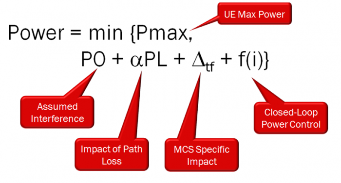
In particular, the power that the UE transmits the PUSCH with is given by:

The power control formula for the uplink for the PUSCH in LTE can be broken into five key parts. The first part is the amount of additional power that is needed based on the size of the RB allocation. The higher the number of RBs, the higher the power that is required.
The second part is called P0. It is basically the assumed interference that the UE is expected to overcome. P0 is composed of two subcomponents. The first is called P0_Nominal_PUSCH and it is communicated over SIB2. It is valid for all UEs in the cell. The second component is called P0_UE_PUSCH and it is a UE-specific value. It is optional.
The third part of this equation is the Path Loss (PL) and the impact of the PL or Alpha. PL is just calculated, but the Alpha value communicated to the UE in SIB2. If the Alpha value is set to 1, then all of the PL needs to be taken into account in the power control formula. Some vendors might not allow you to change this value, though (as it is hardcoded).
The fourth part is an MCS-specific component. If the eNB wants the UE to adjust its power based on the MCS that is assigned, it will be taken into account here.
Lastly is the f(i) value, which is simply the closed-loop feedback. This is the additional power the UE will add to the transmission based on specific feedback by the eNB.
Hence, for the PUSCH, two parameters affect the UE transmit power, and therefore, our UL RSSI:
a) PO_nominal_PUSCH
b) Alpha.
PUCCH:
The power control formula for the uplink for the PUCCH in LTE can be broken into four key parts. The first part is called P0. It is basically the assumed interference that the UE is expected to overcome. P0 is composed of two subcomponents. The first is called P0_Nominal_PUCCH and it is communicated over SIB2. It is valid for all UEs in the cell. The second component is called P0_UE_PUSCH and it is a UE-specific value. It is optional. The second part of this equation is the Path Loss (PL) and the impact of the PL or Alpha (the same value used for the PUSCH – See above-). The third part is an MCS-specific component. If the eNB wants the UE to adjust its power based on the MCS that is assigned, it will be taken into account here. Lastly is the f(i) value, which is simply the closed-loop feedback. This is the additional power the UE will add to the transmission based on specific feedback by the eNB. This value is different for each format type of the PUCCH. A different value is given to the UE in SIB2 for formats 1, 1a, 1b, 2, 2a and 2b.
Hence, the parameters that controls the transmit power in the PUCCH are:
a) PO_nominal_PUCCH
b) Alpha
The higher the value of PUCCH and the higher the value of PUSCH, the more power the UE will transmit, the better the UL BLER, the higher the throughput and the higher the UL SINR. However, in high capacity cell, this might not be true and the opposite effects might be encountered. Examples of such situations are: Airports, events, convention centers, etc. It is recommended to analyze the UL RSSI in these types of venues during high capacity scenarios and adjust accordingly. Bear in mind that the Alpha value affects both, the PUCCH and the PUSCH.